Foundation
Foundation system broadly refers to the arrangement of structural members below the plinth level that transfer the loads from superstructure to the ground. The function of a building foundation is to support the building by safely distributing all the loads acting on the structure including the weight of the building and foundation, live loads and external loads to the ground.
Foundation shall therefore be designed to contain any settlement in the ground within tolerable limits, have sufficient strength and rigidity to not undergo significant deformation, be stable and durable and neither affect nor be affected by any adjoining structures that are existing or to be built in the future. A basic understanding about suitability of different types of soil, how much load the soil can carry and the types of foundations suitable for different ground conditions will be useful to the reader in the design and construction of the foundation system.
Types of foundation suitable for each type of soil structure identified in north paravur
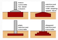
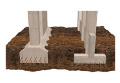
Pad footings (soil type: rock, gravel, sand, silt)
Pad footings (pad foundations) are normally used to support an individual point load, such as from a structural column. A reinforced concrete or mass (unreinforced) concrete slab or pad is provided at the bottom to spread out the load.
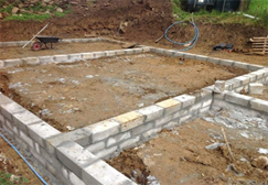
Strip footings (soil type: gravel, sand, silt)
Made up of mass concrete or reinforced concrete, or stone or brick masonry, strip footings (strip foundations) are used to support a linear loads, such as along a load-bearing wall or beam or for a row of columns so closely spaced that individual pad foundations would nearly touch each other. Strip width depends on the strength of soil and the load. Narrow strip footings with minimum strip width of 500mm can be good enough for two storey building in normally good soil. However, wide strip footings need to be used for weak soils.
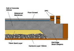
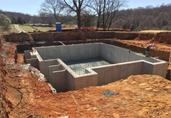
Raft foundations (soil type: hard clay)
Raft foundations are used in situations to spread the load of the structure over a large area when the soil is weak or when column loads are close together and individual pad foundations would interact or when a basement is required. Raft consists of a reinforced concrete slab normally extending over the entire plinth area of the structure. Ribs or beams may be incorporated into the foundation to stiffen the slab. The rigidity given to the raft also helps accommodating differential settlement.
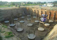
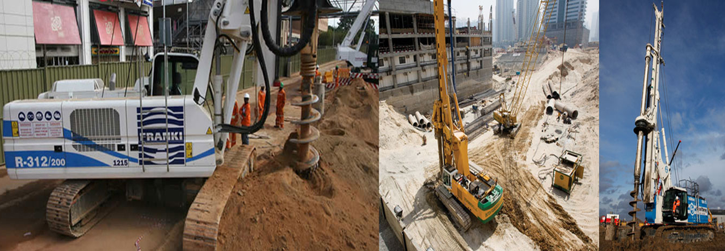
Pile foundations (soil type: soft clay)
Piles are relatively long, slender columns made of concrete, steel or timber, used to transmit foundation loads to a deeper soil or rock layer having adequate strength when shallow soil layers are too weak to use shallow foundations. Generally adopted types of Pile foundations are End Bearing Piles, Under Ream Piles (friction piles), Sand piling, Bamboo piling, Coconut trunk piling.
End Bearing Piles
End-bearing piles develop most of their load-bearing capacity at the toe of the pile, bearing on a hard layer of rock or very dense soil and gravel. The pile transmits the load through soft, compressible strata directly onto firm strata. This type of pile therefore acts in the same way as a column.
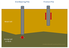
Under Ream Piles (Friction Piles)
Friction (or floating) piles develop most of the pile-bearing capacity by shear stresses along the sides of the pile, and are suitable where harder layers are too deep to reach economically. The pile transmits the load to surrounding soil by adhesion or friction between the surface of the pile and soil, which in effect lowers the bulb of pressure. In other words, the whole surface of the pile (cylindrical in shape) works to transfer the forces to the soil.
Sand Piling
Developed in Japan, the sand compaction pile (SCP) method is used to strengthen soft ground by installing sand or a similar material into the soft ground via a casing pipe and vibrating the sand to produce firmly compacted sand piles in the ground.
Bamboo Piling
Bamboo of more shell thickness up to 20mm to 30mm and 100mm to 150mm dia can be used for Pile Foundation. It is widely used more than 200years ago. Straight Bamboo will be derived in to the BC soil/ Paddy field with water stagnation up to the Hard Strata of Soil. Green Bamboo immediately after cutting will be used for this. Wooden Hammer will be used for inserting the bamboo in soil. Distance between two Bamboo piles will be 200mm to 350mm according to the load coming on the foundation. If this Bamboo Piles are for the construction of foundation of a Building, we have to insert Bamboo in the foundation Trench. Once Piling is completed top level of all bamboo will be made equal by Hammering. Bamboo of same dia and less dia will be cut vertically into two pieces and by using this we have to make a thick layer above bamboo piles. A layer of 150mm thick Concrete with Steel Reinforcement (Concrete Raft) will take the load of a two floor Residential Building.
Coconut Trunk Piling
Coconut trunk piling is a very cheap and strong method of piling in marshy areas where soil strength is very low, this technique is very effective in transferring the load of the structure to a strong substrata, the only thing to be made sure is that the pile should be below ground water level.
Different types of materials used for foundation
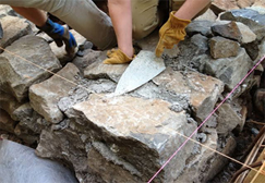
Stone: Stones as building foundation material proved to be strong, durable and economical to use if they are available near the building site. Stones for Random Rubble Masonry should be as per the following specification – The size of the stone shall be normally varied from 0.05 to 0.01 cum. No stone larger than the maximum specified size of 0.05 cum. should be used (in general). The stones shall be taken from quarries approved from the geological department. Stone masonry can be done in 2 ways.
- Dry Rubble Masonry: Where the Stones are packed in the foundation trench such that the voids between each layer is minimised. And later the voids in stone packing to be filled with available sand or red earth available at site and the pockets are filled with the slurry of water and sand or earth.
- Random Rubble Masonry in Cement Mortar: In RRM each layer of stones are laid over a bed of cement sand mortar with ratio 1:6.
Reinforced Cement Concrete (RCC): Concrete is the most popular foundation material among all other building foundation materials because it is hard, durable and strong in compression. Concrete does not affect by moisture and can be made nearly watertight for basement walls. It can easily be casted in any shape required for each foundation. RCC Foundation is the part of structure below plinth level up to the soil. It is in direct contact of soil and transmits load of super structure to soil. Generally it is below the ground level. Steel is the most popular reinforcing material. Concrete is made by using Cement, Sand, Aggregate and Water. Normally concrete is specified in Grade of Concrete (Grades can be M20, M25 etc.). Volumetric proportion of 1:1.5:3 will give M20 concrete. Cement for Foundation concrete can be PPC (Portland Pozzolana Cement). Aggregates for foundation are classified to fine aggregates and coarse aggregates.
Aggregates cover 60 – 80 % volume of concrete mix. Its main function is to provide compressive strength and bulk to concrete. Amount of aggregates are used in any concrete are selected for their durability, strength, workability, and ability to receive finishes. For making strong and durable concrete, and aggregates need to be clean, hard, strong particles free of absorbed chemicals or coatings of clay and other fine materials that could cause the deterioration of concrete. Normally concrete in foundation is used along with Reinforcement steel in order to strengthen and hold the concrete during tension. Reinforcement steel to be minimum Fe 500D.
Solid concrete block wall
Block made of concrete can be used to construct attractive and durable foundation walls. Concrete block eliminates the need for unnecessary formwork and, because of their large size; concrete blocks will lay up faster than bricks. Its major disadvantage is that concrete block walls are difficult to make watertight than a concrete wall and do not resist lateral forces.
Cost wise comparison of different types of foundation
End bearing piles
| Type of Methods | Direct Mud Circulation Method (DMC) | Rotary piling method |
|---|---|---|
| Diameter of the pile | Rate per meter | Rate per meter |
| DMC 500mm | Rs. 4500/ m | Rs 5000/ m |
| DMC 600mm | Rs 5040/ m | Rs 5540/ m |
| DMC 700mm | Rs 5600/ m | Rs 6100/ m |
| DMC 800mm | Rs 6300/ m | Rs 6800/ m |
| Mobilization charge = Approximate Rs. 35000/- | ||
| Muck removal @ Rs 200/m | ||
| Steel Reinforcement cost including Fabrication @ Rs 65000/MT | ||
| Types of Pile Foundation | Rate (Approx.) |
|---|---|
| Under reamed piles (friction piles) – up to 12m | Rs. 3000 per meter + Steel Reinforcement cost |
| depth | including Fabrication @ Rs 65000/MT |
| Sand piling – 3m depth | Rs. 45/m for 100 mm diameter |
| Bamboo piling | Cost of Bamboo @ Rs 70/ m, Labour = Rs 1500/ Man days |
| SCoconut trunk piling | Cost of Coconut Tree @ Rs 150/ m, Labour = Rs 1500/ Man days |
| Cost of pile cap will be extra for pile foundations RCC M25 @ Rs 15000/ m3 + Steel Reinforcement @ Rs 65000/MT | |
| Footings – raft, strip, isolated | RCC M25 @ Rs 15,000/ m3 |
| Rubble foundation | Dry pack (DRR) @ Rs 5000/m3 Random rubble masonry in cement mortar @ Rs 6500/m3 |
Innovative ideas in foundation construction
Floating foundation: A floating foundation is a type of foundation constructed by excavating the soil in such a way that the weight of structure built on the soil is nearly equal to the total weight of the soil excavated from the ground including the weight water in the soil before the construction of structure. The main principle of floating foundation is to balance the weight of removed soil by a structure of same weight which causes zero settlement to the structure. So, this foundation is also called as balancing raft foundation.
Floating foundations are desirable for the following types of soils:
- Soils which are having good shear strength but having a problem of large settlements and differential settlements under heavy loads. In which case, floating foundation can reduce the settlement values to greater extent.
- Soils which are having low shear strength and there is no hard layer of soil at reasonable depth. Here also, floating foundation helps to reduce the shear stresses to satisfactory level and hence settlement is prevented.
Post tensioned foundation: A post-tensioned foundation is a concrete slab foundation that is reinforced with stranded steel cables that are tensioned after the Post-tensioned cable diagram concrete hardens. The stranded cables are slid inside of plastic-sheathing, which prevents the stranded steel tendons from touching the concrete. When the foundation/concrete has sufficiently hardened/cured, the plastic-sheathing is stretched/elongated. Stretching or elongating the post-tensioned cables applies significant force to the concrete system, lifting the slab into a compressed state, which reduces the negative effects from tensile forces (cracking).
The most common slab configuration encounter has the following characteristics:
- 24-30 inch deep perimeter footer/beams with interior beams of the same depth (they look like trenches). Each of the beams has an upper and lower tendon (commonly referred to as a draped tendon).
- The sheathed tendons are generally supported on plastic chairs spaced at 4 feet on centre. The interior pads are typically constructed to be 4-5 inches thick
- 12-14 inch wide beams around the perimeter and interior of the slab
Post-Tensioned foundations are relatively more suitable in poor soil conditions and have simpler installation procedure when compared to a conventional rebar foundation as it is easier for the concrete crew to pour the concrete due to the spacing and arrangement of the tendons, minimizing displacement from foot traffic. The Lighter overall structure compared to that of all steel reinforcing bar foundation and can be more economical as well as easier to inspect and repair. Despite of all the advantages, such foundations tend to develop unsightly curing cracks.
Design of foundations
It would be prudent to have a general idea of the subsoil condition of the site before deciding on the location of the house and demarcating it on the plan sent for building approval by the authorities. Preliminary information can be gathered from a trial pit dug at the location. However for the design of foundations, more detailed investigations may be required as given below.
Step1. Ascertain the Nature of the Ground
- Nature of the ground, e.g. whether the ground is natural, flat or sloping or having rapid undulations, cut or reclaimed, located close to a marshy or low lying land presence of any significant features such as, old fills, wells, pits or quarries or variations within the site that may significantly affect the foundation design.
- If the land shows any such complexities, seek professional advice of a geotechnical engineer who may conduct necessary studies to ascertain the parameters for foundation design.
- However, if the ground is judged to be free from any such complexities and having understood the risks of ignoring any complexities, can use the following procedure for the design of foundation.
Step 2. Ascertain the Subsoil Profile and Bearing Stratum
- It is essential that the foundation is placed on a soil layer having the required bearing capacity and sufficiently below the design final ground level in order to minimize the impact of any erosion and to maximize the lateral restraint from surrounding soil.
- For deciding the appropriate depth of foundation, it is necessary to know the type and strength of soil layers, ground water table and its possible fluctuations, etc.,
- Dig a trial pit within the planned building area, preferably at or close to the location of columns or walls, to a minimum depth of 1.0m below the planned ground level, but deep enough to penetrate into a hard soil layer suitable as the bearing stratum.
- The foundation level must be decided ensuring that the subsoil underlying the foundation is equally strong or stronger than the bearing stratum to some further depth, say at least another 1.0~1.5 meters.
- Soil may be identified visually by digging further if practical or as a crude test, by probing the ground below with a crow bar or a metal rod and observing the resistance.
- Observe the ground water table if encountered within the pit after the water level has stabilized.
- Observe whether the soil consists mostly of gravel, sand or clay and how the soil is naturally compacted (loose, medium or dense) or how stiff (soft, firm or stiff) it is.